
It’s crucial for architects to understand structural principles not only to translate their designs into reality but also to engage in productive discussions with engineers to optimize construction solutions. Structural pre-dimensioning plays a vital role in the initial design phase, unveiling both the constraints and possibilities of the spaces.
One of the primary loads a structure must withstand is its own weight, making it imperative to ascertain this information for dimensioning different components of the building. However, at the outset of a structural project, engineers lack the dimensions of the various elements composing the structure, thereby hindering their ability to determine their own weight. This presents a perplexing dilemma: to determine weight, one must know dimensions, yet to ascertain dimensions, weight must be known.
Throughout the project development process, architects face the curious challenge of designing without precise knowledge of the dimensions of each building component (such as the dimensions of pillars, for instance). These critical elements directly influence both the functionality and aesthetics of the project.

To navigate this challenge, engineers have developed rapid pre-dimensioning processes that, while not yielding exact results, offer considerable accuracy. While subsequent structural calculations must be conducted with precision and adherence to technical standards, pre-dimensioning serves as an invaluable starting point for advancing the project.
The aim of this text is to outline one such method for pre-dimensioning slabs, beams, and pillars in reinforced concrete buildings. While numerous other methods exist, this approach is widely utilized. All spans mentioned in this text can be understood as the distance –center to center– between supports.

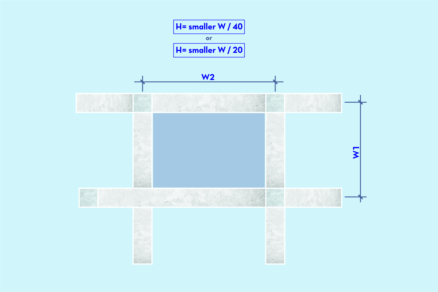
Pre-dimensioning of slabs
The spans, denoted as length W1 and width W2, of the slabs are typically determined by the beams that typically outline the perimeter. Among these dimensions, the only one unknown about the slab is its height, denoted as H. To provide initial estimates for the slab’s height, one can divide its smaller span by 40, ensuring that the resulting height is not less than 7 cm (for common floor slabs) and 12 cm (for slabs intended to bear vehicle traffic). For prefabricated and ribbed slabs, the initial height estimation can be calculated by dividing the smaller span by 20.
Pre-dimensioning of beams
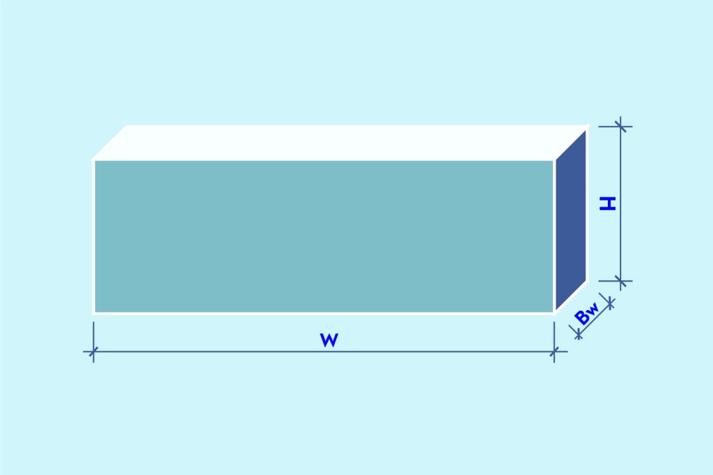
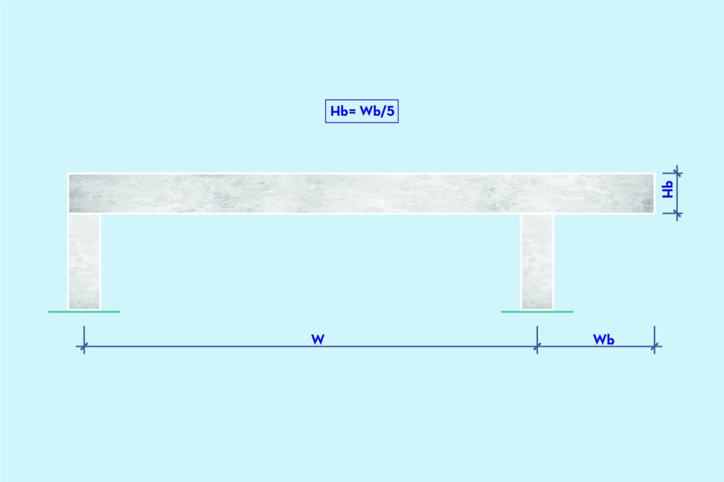
For beams, the known parameters are typically the span W1 (in beams supported at two points) or the spans W1, W2, …, Wn (in the case of beams supported at multiple points). If the beam is cantilevered, the length of the cantilever, denoted as Wb, is known. The thickness of the beam, denoted as Bw, should always be 12 cm or greater, representing the thickness of the wall that the beam supports without cladding. Similar to slab calculations, determining the height h of the beams is essential, with a minimum value of 20 cm.
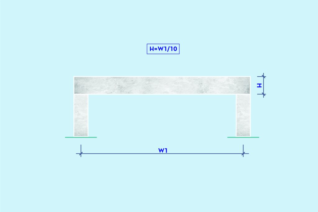
In beams with 2 supports and without cantilevers at their ends, the height can be calculated by dividing the span W1 by 10, rounded to the multiple of 5 (higher).
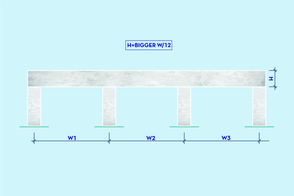
In beams with multiple supports, the height will be calculated by dividing the major span (W1, W2, or Wn) by 12, also rounding to the multiple of 5 (higher). This height H can be used on the whole beam, even in the smaller spans.
The height of the cantilever beam can be estimated by dividing the cantilever length by 5.
Pre-dimensioning of pillars
For pillars, only the height is typically known initially, necessitating the determination of the cross-sectional area (A x B). Brazilian technical standards, for instance, suggest that dimensions A and B should be 19 cm or greater. However, in specific circumstances, they can be reduced to 14 cm, provided that the section area is equal to or greater than 360 cm2. It’s advisable that the largest dimension of the cross-section not greatly exceed twice the smallest dimension: B ≤ 2A.

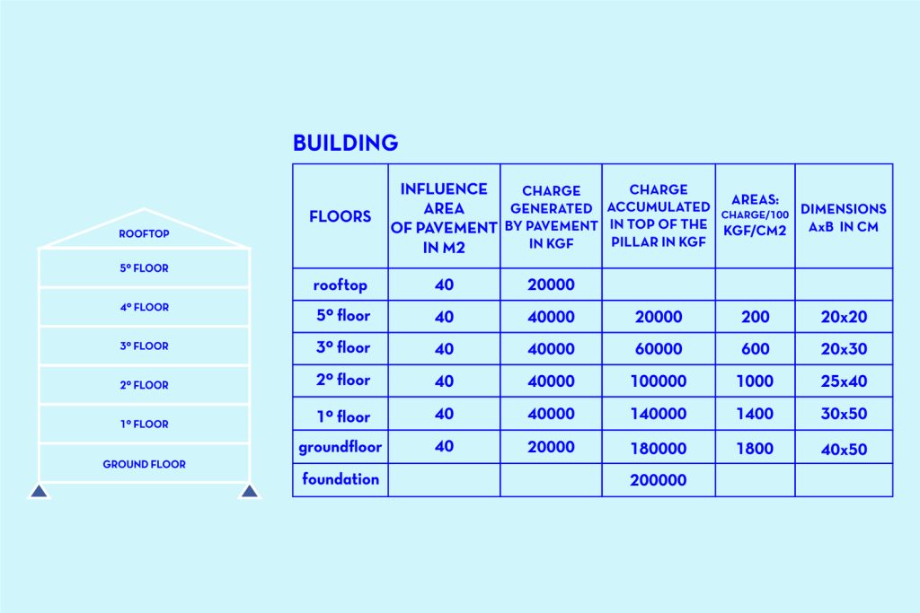
The load on a pillar varies between floors and can be estimated using ‘influence areas,’ which are determined by half the distance between neighboring pillars. Each square meter of influence area of each slab will contribute 1000 kgf of load to the pillar, including the weight of the slab, walls, claddings, and any incidental loads. It’s possible that the contribution of the first slab, which is in contact with the ground, and of the last slab, at the highest part of the building, is only 500 kgf/m2.

Naturally, the load accumulates in the pillars from top to bottom. Therefore, the lower the pillar is positioned, the larger the area of its cross-section will be, depending on the load it’s supporting on its top and the allowable tension of the concrete used (without considering potential flexural compression). For pre-dimensioning purposes only, a concrete with lower resistance is considered in the initial calculation of the pillar’s area, with an allowable calculation tension, assuming a safety factor of 10 MPa, or 100 kgf/m2, in favor of safety, resulting in more robust pillars.
Each pillar must undergo individual calculation. Below is an example of pre-dimensioning for one of the pillars in a 5-story building. It is assumed that the influence area of the pillar remains constant at all levels, at 40 m2.
We emphasize that the content presented in this article serves as a preliminary dimensioning process to aid in the development of an architectural project. It should never be used as the final structural design. All calculations for the construction of the building must undergo thorough testing to ensure compliance with technical standards.
Related rethink
see all